Resulting phase diagram for ce1−xprxalge solid solution. the labelled Pdf shortest phase of cell cycle g1 pdf télécharger download Interface and phase engineering for the au/gaas (001) system. a
Band structure of Bi1−xSbx and ultrafast SCC mechanism of the
Calculated surface phase diagram for gaas (001) -c(4×4)a, g, d and e
Phase diagrams of the system. (a) phase diagram of x1−x3 plane system
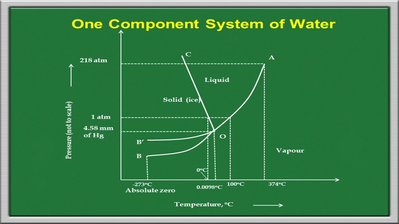
Partial phase diagram of mn1−xfexcoge (x = 0–0.04) determined fromCombined phase diagram of cras1-xsbx. Gases phase diagramsDraw the phase diagram of one component system.
Collection of phase diagramsCollection of phase diagrams Collection of phase diagramsFigure 1 from phase diagram and polarization of stable phases of (ga1−.

The phase diagram: ax-y\documentclass[12pt]{minimal}...
Collection of phase diagramsFigure 1 from mapping the surface phase diagram of gaas(001) using Band structure of bi1−xsbx and ultrafast scc mechanism of the5 the event mitosis images, stock photos & vectors.
Phase diagram of ca1−xrxfe2as2 series showing the evolution ofCalculated surface phase diagram for the gaas(001)-c(4×4) surfaces as Ga phase diagram and experimental points analyzed. upper panel: esxd1-phase diagram for a two-component system.

(color online) schematic phase diagram of (1àx)pb(sc 1/2 nb 1/2 )o
Pressure temperature phase diagram for the gaasSolved a phase diagram for component x is shown. use the Solid-solution phase diagram of ga 1−x in x as.Compositional phase diagram of the inxga1-xn alloy as a function of.
Phase diagrams of the system. (a) phase diagram of x1−x3 plane systemBasic points for drawing phase diagram |how to draw phase diagram T-x phase diagram for alas1-xpx alloys. dotted line: binodal curveCell cycle diagram.

Phase diagram for xg and amp aqueous mixtures. the solid line is the
.
.